We welcome you to browse our RESOURCES or search for that special need. If you are unable to find the information that your project requires,
please Contact Us >.
Wind Zone Map
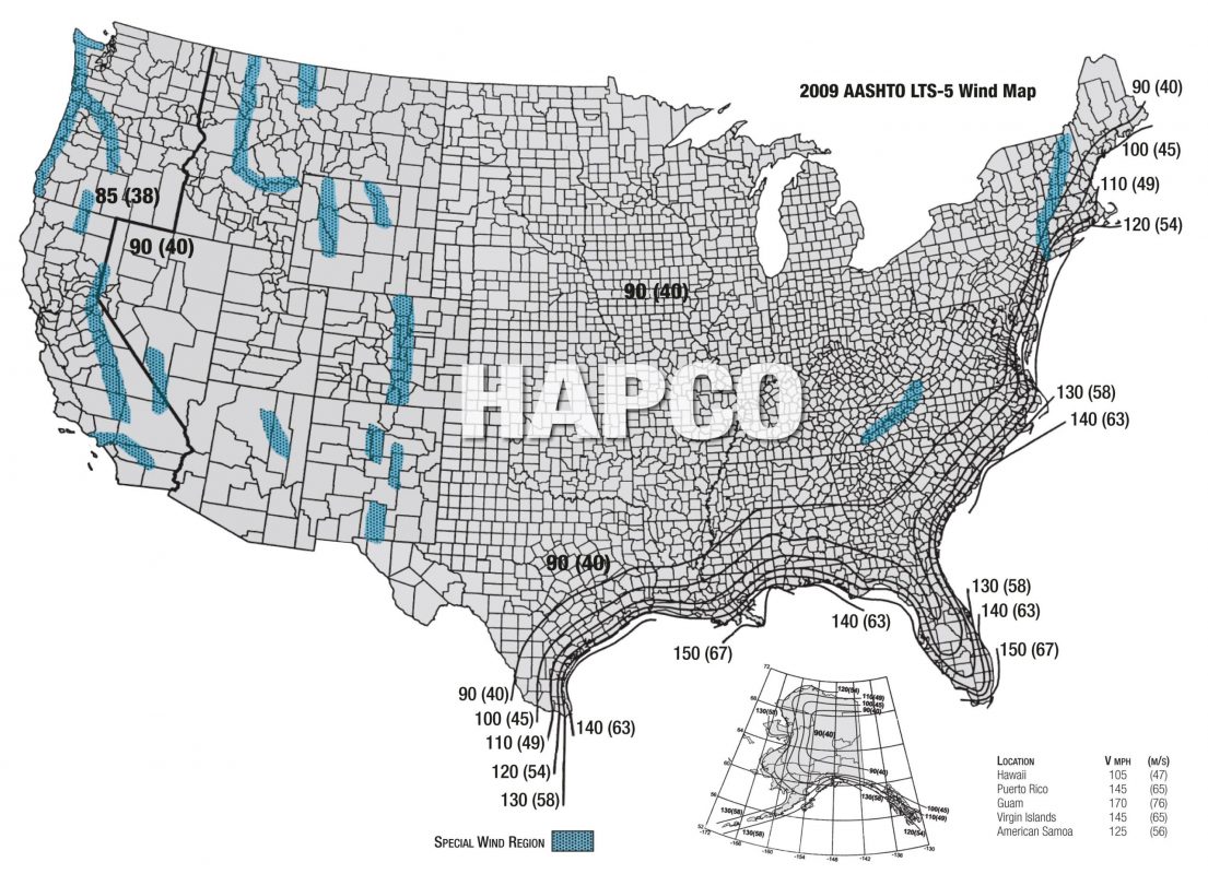
Wind Velocity Selection
2009 AASHTO LTS-5 specification 3-second gust basic wind speeds (mph) with gust effect factor (G) of 1.14 and 25 year design life wind map (ASCE 7-05) is shown below. This wind map should be used to determine wind velocity for your specific location. If you are located between two different velocity isotach lines, the higher velocity should be used.
Hapco has learned from years of experience that there are local isolated high wind conditions that can be devastating to poles and luminaires not designed for such conditions. Additionally, constant winds in the 10-25 mph range can severely damage certain poles and luminaires by vibration.
Vibration is a local, site specific condition that should not be overlooked when selecting a pole. Destructive vibration is NOT an indication of substandard material, workmanship, or pole design. Please advise Hapco of any unusual wind conditions prior to purchase of poles. More robust poles and/or vibration dampers may be necessary to avoid wind damage.
Pole failures as a result of wind induced vibration are NOT covered under manufacturer’s warranty. Please reference “LIFETIME WARRANTY” and “WIND-INDUCED VIBRATION” for Hapco’s policy regarding vibration.
Warranties
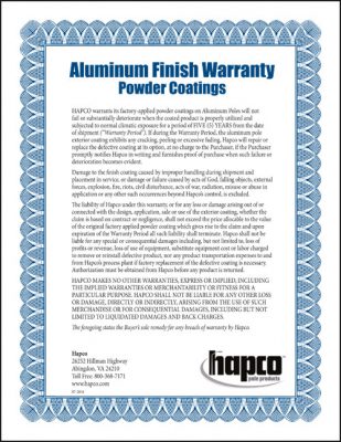
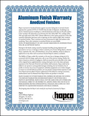
Click on a Hapco Warranty image below to open a high resolution PDF in a new tab.
General Information
Click on an image below to open a high resolution PDF in a new tab.
Informational Videos
Locking Handhole Cover
An Effective Deterrence Against Copper Theft. Hapco’s heavy-duty, Locking Handhole Cover creates secure access to pole wiring while maintaining a sleek and aesthetic look.
Vibration Isolating Arm
The Vibration Isolating Arm support system’s natural frequency is below the range of frequencies that result in damage to the light fixture.
Installation Instructions
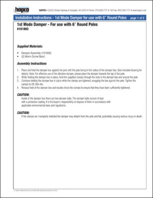
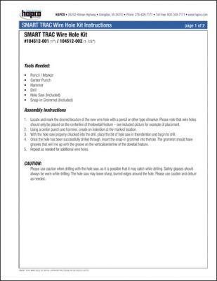
Click on an image below to open a high resolution PDF in a new tab.
Aluminum Light Pole Specifications
Pole Shaft
The shaft shall be constructed of seamless extruded tube of Aluminum Alloy 6063(round shafts) or Aluminum Alloy 6XXX (square shafts) per the requirements of ASTM B221 of sufficient nominal thickness to meet the design requirements without the use of internal reinforcing sleeves. No longitudinal shaft welds shall be allowed. The shaft shall be full-length heat treated after welding to produce a T6 temper in round shafts and a T5 temper in square shafts. The heat-treating oven used shall be certified to meet the requirements of ASTM B597 and Mil-H-6088 specifications. An aluminum pole cap utilizing stainless steel attaching screws will be provided when required.
Pole Arms
The pole arms will be constructed of seamless extruded tube of Aluminum Alloy 6063 per the requirements of ASTM B221. Arms shall be full-length heat treated after welding to produce a T6 temper. Attachment pole plates shall be of Aluminum Alloy of T6 temper with stainless steel attaching hardware.
Anchor Base - Round Shafts
4-Bolt Base
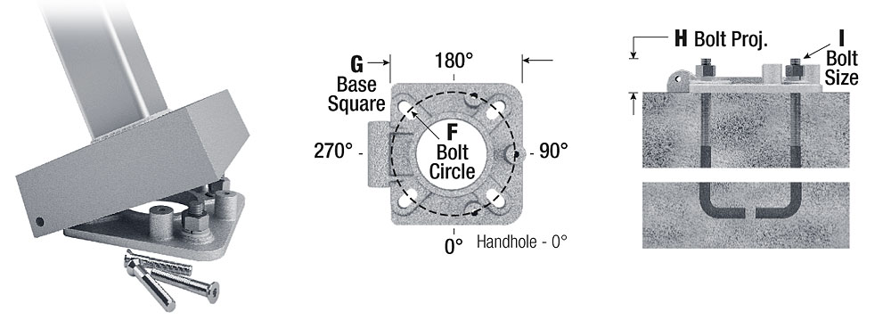
The 4-Bolt base flange for attachment to the foundation or to the transformer base shall be of cast Aluminum Alloy 356-T6. Base flange shall be joined to pole shaft by means of complete circumferential welds; externally at the top of flange and internally at bottom of shaft tube. Four anchor bolt covers of cast Aluminum Alloy 356-F with stainless steel hex head attaching screws shall be provided.
3-Bolt-Base
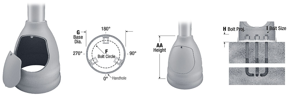
The 3-Bolt base flange shall be of cast Aluminum Alloy 356-T6 with spun aluminum base cover and stainless steel hex head attaching screws. Base flange shall be joined to pole shaft by means of complete circumferential welds; externally at the top of flange and internally at bottom of shaft tube.
Hinged Base
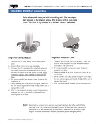
Hinged cast aluminum base flange of Alloy 356-T6 with 2-piece cast aluminum base cover and stainless steel hex head attaching screws. Base flange shall be joined to pole shaft by means of complete circumferential welds; externally at the top of flange and internally at bottom of shaft tube. The hinge mechanism is engaged by removal of the 2-piece cover and two front anchor bolt nuts.
Beehive Base
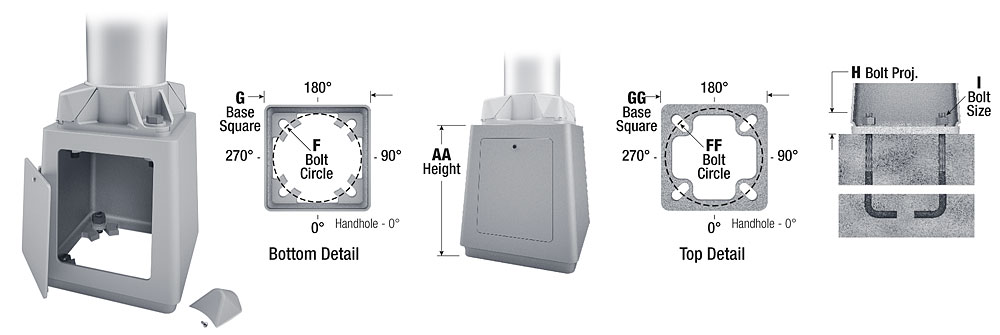
The Beehive cast aluminum transformer base shall be of Alloy 356-T6 with an aluminum door and stainless steel attaching screws. Base shall be joined to pole shaft by means of complete circumferential weld.
Direct Buried
Direct Buried aluminum poles are designed for embed installations. Poles with butt diameters of 6″ and larger shall be provided with an anti-rotational device by means of partial flattening the butt of the pole into an oval cross-section. A wiring provision will be provided 24″ below ground line. Soil conditions vary by site, therefore foundation requirements should be determined by a qualified Structural Engineer with knowledge of jobsite soil conditions.
Transformer Base (T-Base)
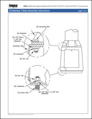
The T-Base shall be a casting of Aluminum Alloy 356-T6 with removable access door held in place with one stainless steel screw. The base shall be 17″ tall with an access door 11-3/4″ high, 9-1/4″ wide at the top and 9-3/4″ wide at the bottom. It shall connect to 1″ diameter anchorage. Three bases with bolt circles ranging from 10″ to 17-1/4″ can be used with shafts in size from 6″ to 10″ diameter (dependent on their proper application and specific loading restrictions). The bases shall meet 2009 AASHTO breakaway requirements. Four (4) 1″ diameter galvanized steel hex-head machine bolts with nuts and washers shall be supplied to attach the transformer bases to the base flange of the pole shaft. Eight (8) 1/2″ thick x 2-3/4″ diameter galvanized steel heavy washers shall be provided to properly distribute the bolt forces in the top and bottom flanges of the transformer base.
Anchor Base - Square Shafts
4-Bolt Base
The 4-Bolt cast aluminum base flange shall be constructed of Alloy 356-T6 with aluminum snap-in bolt covers.
Hinged Base
The Hinged cast aluminum base flange shall be constructed of Alloy 356-T6 with three (3) stainless steel screws. Base flange shall be joined to pole shaft by means of complete circumferential welds; externally at the top of flange and internally at bottom of shaft tube. The Hinge mechanism is engaged by removal of the three (3) securing screws.
Handhole - Round Shafts
4″-5″ Butt Diameters
4″-5″ butt diameter poles shall feature a 2″ x 4″ handhole with curved lap style aluminum door and two (2) stainless steel self-tapping attaching screws. A grounding provision incorporating a tapped ¼”-20NC hole is provided opposite the handhole.
6″ Butt Diameter
6″ butt diameter poles shall feature a reinforced, 3″ x 5″ curved cast aluminum frame (Alloy 356-T6) with aluminum door and two (2) stainless steel hex head screws. A grounding provision incorporating a 3/8″ diameter hole is provided opposite the handhole.
7″+ Butt Diameters
7″ and larger butt diameter poles shall feature a reinforced, 4″ x 6″ curved cast aluminum frame (Alloy 356-T6) with aluminum door and two (2) stainless steel hex head screws. Reinforced frame will contain a tapped 3/8″-16NC grounding provision.
Handhole - Square Shafts
4″-5″ Base Squares
4″-5″ square poles shall feature a 2″ x 4″ handhole with square lap style aluminum door and two (2) Stainless Steel self-tapping attaching screws. A 1/4″-20NC grounding provision is provided opposite the handhole.
6″+ Base Squares
6″ and larger square poles shall feature a 3″ x 5″ handhole with square lap style aluminum door and two (2) Stainless Steel self-tapping attaching screws. A 1/4″-20NC grounding provision is provided opposite the handhole.
Handhole - Poles with Arms
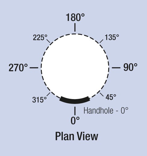
Poles with single arms will contain a handhole that is located 90 degrees clockwise from the plane of the bracket arm as viewed from the top of the pole. Twin arm poles will contain a handhole that is located 90 degrees from the plane of both bracket arms.
Anchorage
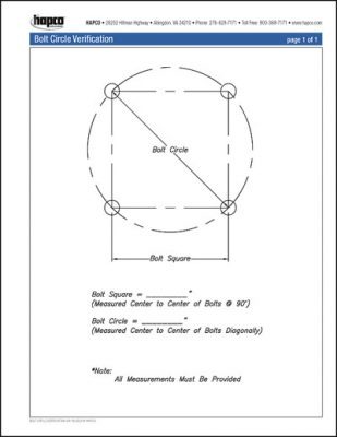
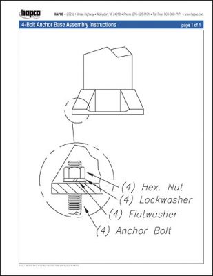
Each anchor base pole shall be supplied with anchor bolts. Steel bolts conforming to AASHTO M314-90 Grade 55 with the threaded end galvanized a minimum of 10″ per ASTM A153 and a right angle hook at the unthreaded end. Each bolt shall include one (1) hex nut, lock washer, and flat washer, with all components being of galvanized steel. A bolt circle template will be provided.
Miscellaneous Hardware
Excluding anchorage hardware, all nuts, bolts, and washers used in the fabrication of the pole shall be Grade 18-8 stainless steel.
Grounding
Each pole shaft shall contain an internal ground provision for the purpose of attaching a grounding connector.
Welding
All welding is performed by gas metal arc welding in accordance with American Welding Society (AWS) Specification D1.2, Structural Welding Code – Aluminum, or Canadian Standards Association (CSA) W47.2 Certification of Companies for Fusion Welding of Aluminum.
Inspection and Packaging
Each coated part shall be inspected for appearance uniformity and appropriate coating mil thickness. Coated product shall be spiral wrapped with cross woven textile, polyethylene film or burlap material of sufficient tensile and elongation that exceed required characteristics to ensure protection during handling and shipping. The product shall be bundled with sufficient dunnage and strapping to prevent damage during shipment.
Satin Finish
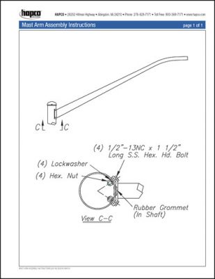
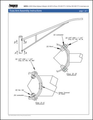
Pole shafts specified with the -01 and -02 Satin finish designations shall be provided a uniform brushed aluminum natural finish achieved by utilizing specially formulated abrasives in a multi-pass, rotary sanding operation. Davit Arms shall match the shaft finish. Mast, Truss, Bullhorn, and Cross Arms shall be provided with a satin etched finish. All materials shall be cleaned and free from dents and unsightly scratches.
Powder Coat - Surface Preparation
Pole shafts shall be satin ground, chemically etched, sanded or shot blasted to ensure proper powder coat surface adhesion. To ensure that the prepared parts are kept clean and not exposed to dirt, dust, grease or oil and to ensure maximum powder coat adhesion, the product shall proceed continuously and immediately to the powder coating process within the same facility where the poles and arms are manufactured.
Powder Coating
Powder coating material shall be a thermosetting polyester powder. A minimum coating thickness of 2.0 mils shall be maintained for aluminum. Application of powder shall be electrostatically applied by a closed loop automated powder coating system featuring twelve automatic spray guns with computerized controls and positioners to assure mil thickness conformance. The powder coating system shall employ a powder recovery system utilizing closed loop quick-change technology to achieve efficient and contamination free color changes. The powder shall be applied only when both the ambient and part temperatures are 50 degrees F. or above. Once powder coated, the product shall proceed through a curing oven operating at 400 degrees Fahrenheit that has been surveyed and certified for temperature uniformity. The product shall move continuously through the oven from beginning to end and shall attain the appropriate time at temperature to cure the finish in accordance with the paint manufacturer’s recommendations. Once oven cured, the product shall move immediately to and continuously through a forced air cooling tunnel designed to restore the product to acceptable packaging temperature prior to inspection and packaging. Upon exiting the cooling tunnel the product shall be immediately inspected and packaged.
Note:
These specifications are intended for general information only. To facilitate our commitment to continuous improvement and providing industry-leading products, Hapco reserves the right to change materials and designs without prior notice.
Anchorage Options
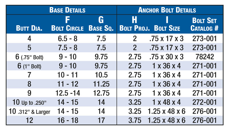
Anchor Bolts

Notes:

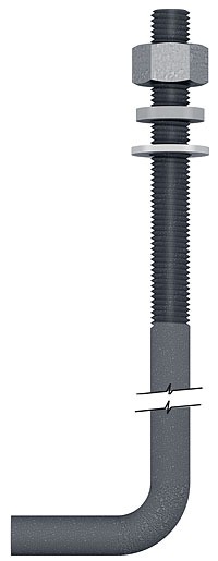
Steel Anchor Bolts conform to AASHTO M314-90 Grade 55. The threaded end will be galvanized a minimum of 10″ per ASTM A153 and contain a right angle hook at the unthreaded end.

Notes:
1. Each catalog number refers to a complete set of bolts. Each bolt will include one nut, one lockwasher, and one flatwasher (all hardware components of galvanized steel).
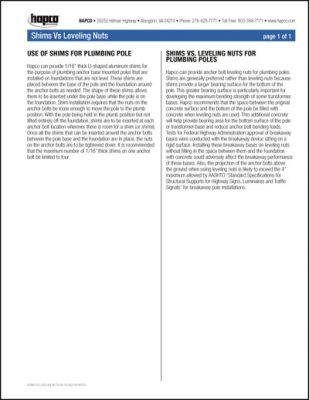
2. To use two nuts per bolt for leveling, change the suffix to “-002” (Example 271-002). “-002” Kits will contain two nuts, two flatwashers, and one lockwasher per bolt. If leveling nuts are used, the pole base should be directly supported in full contact by a high quality, structural, non-shrink grout with a minimum 28 day compressive strength of 8,000 psi. All bolt projections shown in this catalog are for single nut applications. Different amounts of bolt projection will be required for use with leveling nuts. NOTE: Hapco does not recommend double nut installations (See #4), and stilting the pole base with leveling nuts should never be used with breakaway devices. Leveling nuts interfere with the device’s proper performance, and if so mounted, Hapco will void certification that these devices meet AASHTO breakaway requirements.
3. For Double Nut Kits (Hardware Only, No Bolt), specify “DN” (Example 271-001DN).
4. Hapco recommends leveling shims in lieu of leveling nuts. No grouting is required with leveling shims. Order Part # 51432-001 (3-1/8″W x 3-1/2″L x 1/16″H).
5. Contact Hapco Customer Service for information on Anchor Bolt options (SS – Stainless Steel, FG – Fully Galvanized, etc.).
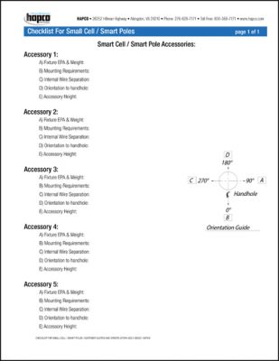
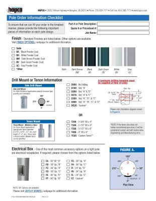
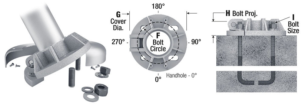
Orientation Guide
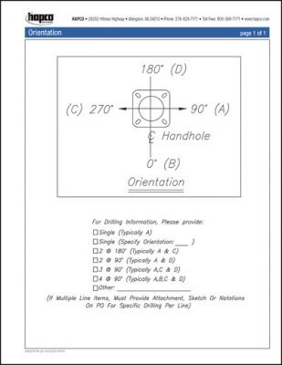
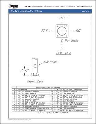
When specifying Pole Accessories, it is important to provide Hapco the correct design orientation. This diagram provides the degree specification of accessories located at various positions on the pole relative to the pole door.
