
Click image to enlarge.
To download a printable file, click PDF Download >
Details
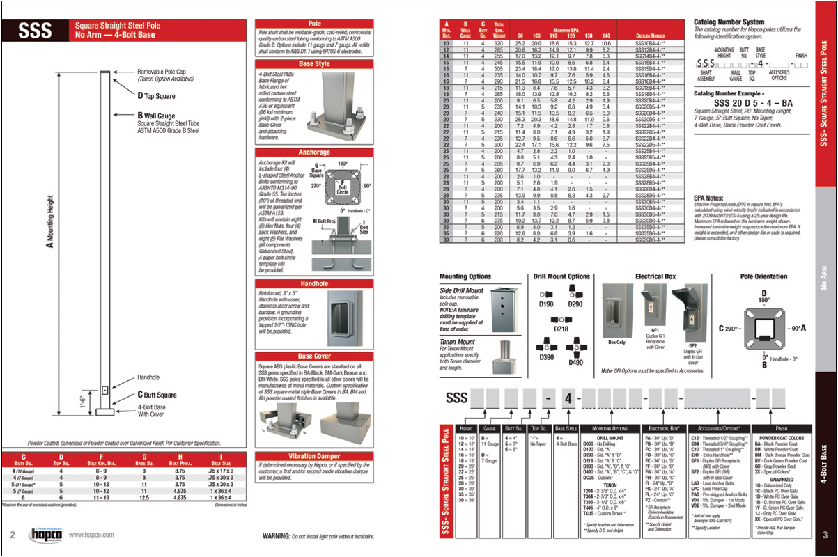
Florida Building Code (FBC) Catalog Pages (WIND SPEEDS TO 180 MPH)
FBC SSS 4-Bolt
Catalog Pages with 2023 FBC Wind Speed Map
SSS No-Arm 4-Bolt Pole Specifications
Pole
Pole shaft shall be weldable-grade, cold-rolled, commercial quality carbon steel tubing conforming to ASTM A500 Grade B. Options include 11 gauge and 7 gauge. All Welds shall conform to AWS D1.1 using ER70S-6 electrodes.
Base Style
4-Bolt Steel Plate Base Flange of fabricated hot rolled carbon steel conforming to ASTM A36 or equivalent (36 ksi minimum yield) with 2-piece Base Cover and attaching hardware. Base Cover will be fabricated from ABS plastic or metal materials.
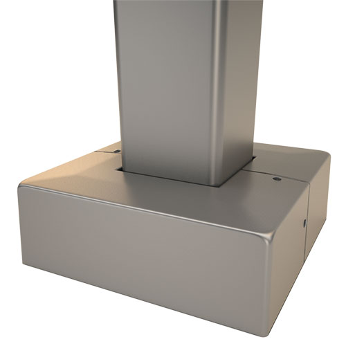
Base Cover
ABS plastic base covers are standard in all SSS poles specified in BA-Black, BM-Dark Bronze, and BH-White. SSS poles specified in all other colors will be manufactured of metal materials. Metal Base Covers for poles in BA, BM and BH can be specified.
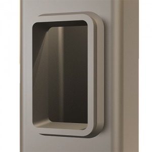
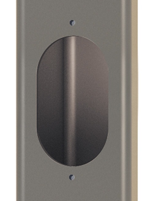
Handhole
Reinforced, 3″ x 5″ Handhole with Cover, Stainless Steel Screw and Backbar. A Grounding Provision incorporating a tapped 1/2″-13NC hole will be welded to the handhole frame.
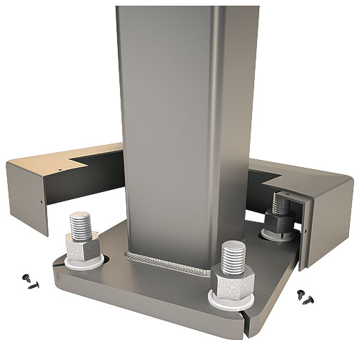
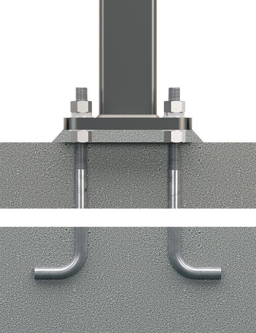
Anchorage
Anchorage Kit will include four (4) L-shaped Steel Anchor Bolts conforming to AASHTO M314-90 Grade 55. Ten inches (10″) of threaded end will be galvanized per ASTM A153. Kits will contain eight (8) Hex Nuts, four (4) Lock Washers, and eight (8) Flat Washers (all components Galvanized Steel). A bolt circle template will be provided.
Base and Anchorage Details
Read More >
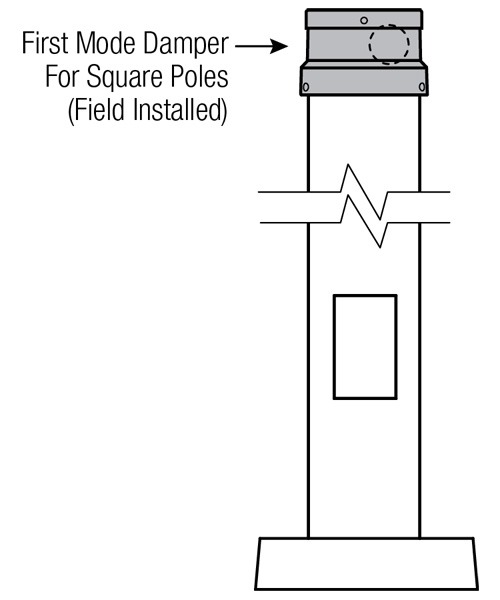
Vibration Damper
If determined necessary by Hapco, a top-mount, field installed First Mode Vibration Damper will be provided. Customer specification of the damper is available.
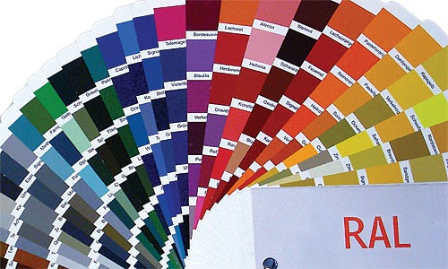
Powder Coat Finish
Coating material will be a thermosetting polyester AAMA 2604 Super Durable powder electrostatically applied, oven cured and bonded in a closed loop, automated system. Minimum thickness of finish will be two (2) mils. Hapco’s Powder Coat Finish Warranty on steel poles is one (1) year.
SSS Pole Orientation
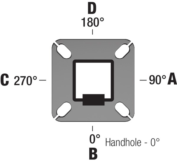
When specifying Pole Accessories, it is important to provide Hapco the correct design orientation. This diagram provides the degree specification and corresponding letter on the pole relative to the pole handhole, and should be used for Drill Mount Options, Electrical Boxes, and Accessories such as Extra Hand Holes and Threaded Couplings.
SSS Mounting Options
Side Drill Mount
For Side Drill Mount applications specify luminaire type, quantity and orientation. A luminaire drilling template must be supplied at time of order.
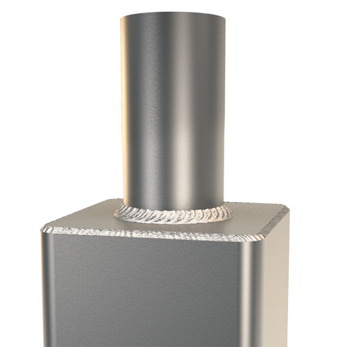
Tenon Mount – Welded
For Tenon Mount applications specify both Tenon diameter (2.375″, 2.875″, 3.5″, 4″, etc.) and length (3″, 4″, 5″, 6″, etc.).
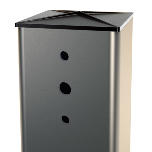
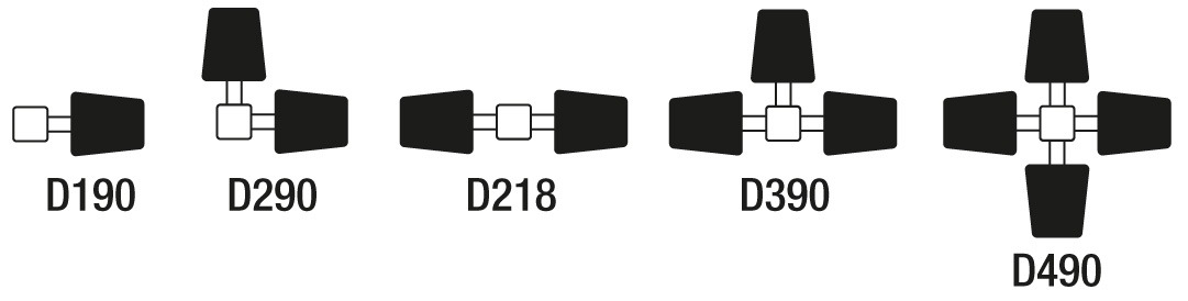
Drill Mount Options
SSS Electrical Box and GFI Options
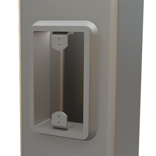
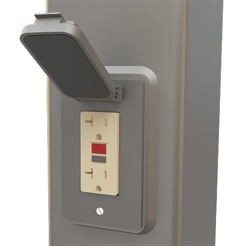
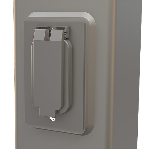
Electrical Box options include Box Only and Boxes with Duplex GFI (WR) Receptacles and Covers. Electrical Boxes are specified with a two-digit notation indicating Height and Orientation (Ex. FA = 30” Up, Side D). Duplex GFI (WR) receptacles with either a Standard Cover (GF1) or In-Use Cover (GF2) can be specified.
GF1
GF1
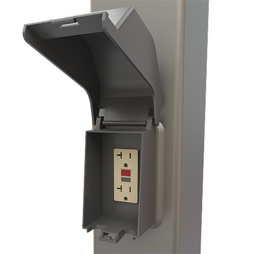
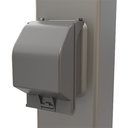
GF2
GF2
SSS Accessories and Options
Couplings
Couplings in ½” (C12), ¾” (C34) and 1” (C10) sizes may be specified. Specify height and orientation with order.
Extra Handhole
Standard handholes are provided centered at 1’-6” up from the base of the poles. Extra Handholes may be specified. Specify height and orientation with order.
Vibration Dampers
First Mode Vibration Dampers can be customer specified.
First Mode
U.S. Patent No. 7871186
Miscellaneous Options
Special options can be customer specified.
LAB – Less Anchor Bolts
LPC – Less Pole Cap
PAB – Pre-shipped Anchor Bolts
Create Custom Specification Drawings
Step-by-step guide generates Steel Pole Specification drawings to match your project requirements.
Download Standard Specification Sheets
| Pole Height | Product No. | Butt Dia | Wall |
|---|---|---|---|
| 10' | SSS10B4-4-** | 4" | 0.120" |
| 12' | SSS12B4-4-** | 4" | 0.120" |
| 14' | SSS14B4-4-** | 4" | 0.120" |
| 15' | SSS15B4-4-** | 4" | 0.120" |
| SSS15D4-4-** | 4" | 0.180" | |
| 16' | SSS16B4-4-** | 4" | 0.120" |
| SSS16D4-4-** | 4" | 0.180" | |
| 18' | SSS18B4-4-** | 4" | 0.120" |
| SSS18D4-4-** | 4" | 0.180" | |
| 20' | SSS20B4-4-** | 4" | 0.120" |
| SSS20B5-4-** | 5" | 0.120" | |
| SSS20D4-4-** | 4" | 0.180" | |
| SSS20D5-4-** | 5" | 0.180" | |
| 22' | SSS22B4-4-** | 4" | 0.120" |
| SSS22B5-4-** | 5" | 0.120" | |
| SSS22D4-4-** | 4" | 0.180" | |
| SSS22D5-4-** | 5" | 0.180" | |
| 25' | SSS25B4-4-** | 4" | 0.120" |
| SSS25B5-4-** | 5" | 0.120" | |
| SSS25D4-4-** | 4" | 0.180" | |
| SSS25D5-4-** | 5" | 0.180" | |
| 28' | SSS28B4-4-** | 4" | 0.120" |
| SSS28B5-4-** | 5" | 0.120" | |
| SSS28D4-4-** | 4" | 0.180" | |
| SSS28D5-4-** | 5" | 0.180" | |
| 30' | SSS30B5-4-** | 5" | 0.120" |
| SSS30D4-4-** | 4" | 0.180" | |
| SSS30D5-4-** | 5" | 0.180" | |
| SSS30D6-4-** | 6" | 0.180" | |
| 35' | SSS35D5-4-** | 5" | 0.180" |
| SSS35D6-4-** | 6" | 0.180" | |
| 39' | SSS39D6-4-** | 6" | 0.180" |